For some upcoming projects, I’ll use the PC817 optocoupler family. But sadly, you don’t always get what you think you’ve bought. So how can you simply check if they work as described in the datasheet? I wanted a quick way to verify parts before building them in.
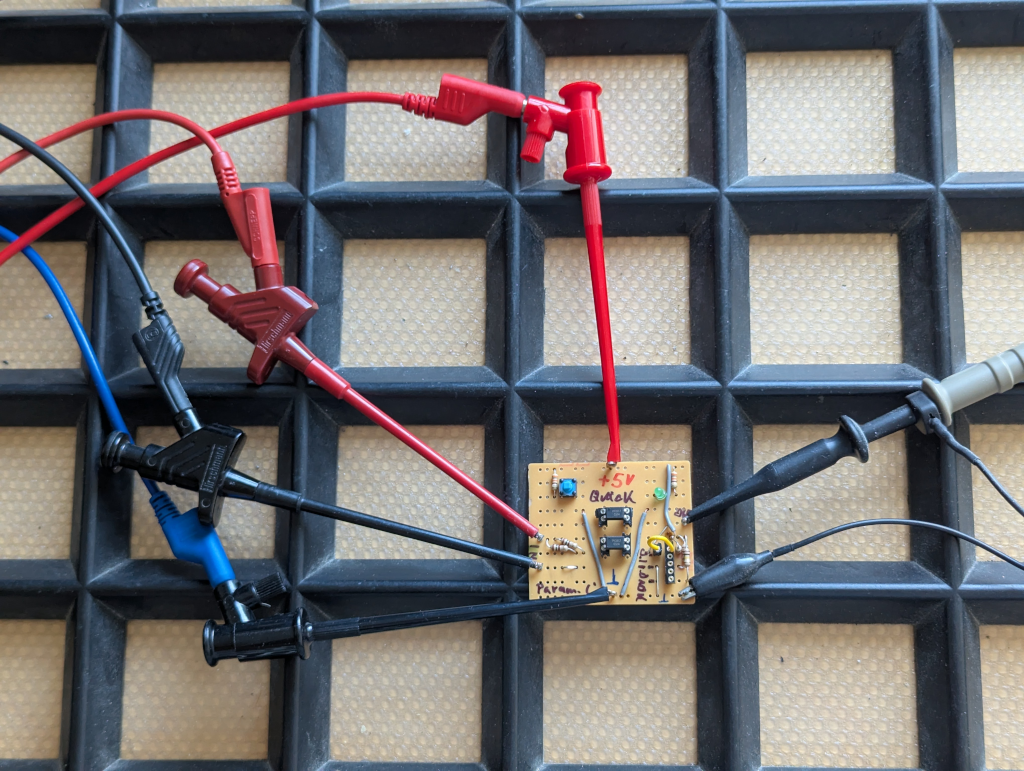
This small tester consists of two independent circuits, runs on 5 V, and does two simple things:
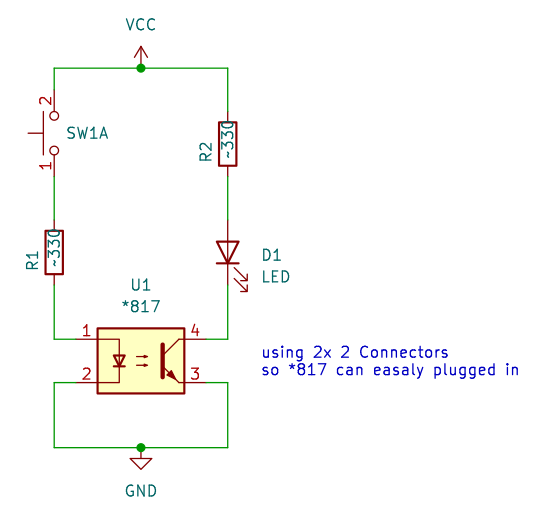
Quick Test – Push the switch, and if the LED lights, the optocoupler basically works.
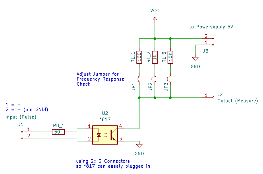
Frequency Test – Based on the circuit from the datasheet. Input impedance is 50 Ω, and the output can be pulled up with 100 Ω, 1 kΩ, or 10 kΩ to see how the device behaves at different frequencies.
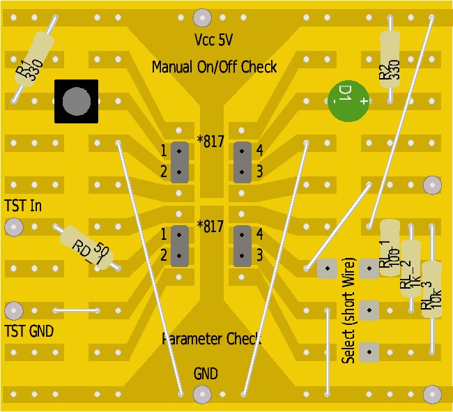
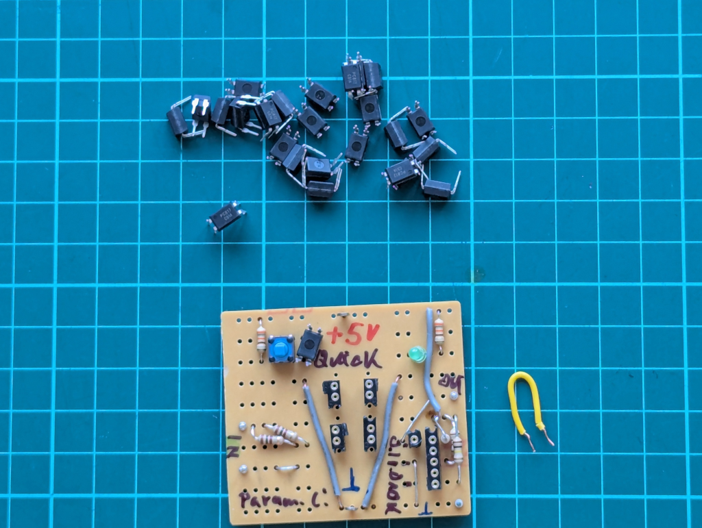
Simple stripboard:
That’s it.
It’s not meant to be fancy—just a tiny 2-hour project to get reliable data and a feel for how different PC817 batches respond.
The project data will be on Gitea – ToGo-Lab, Project ID 0002,
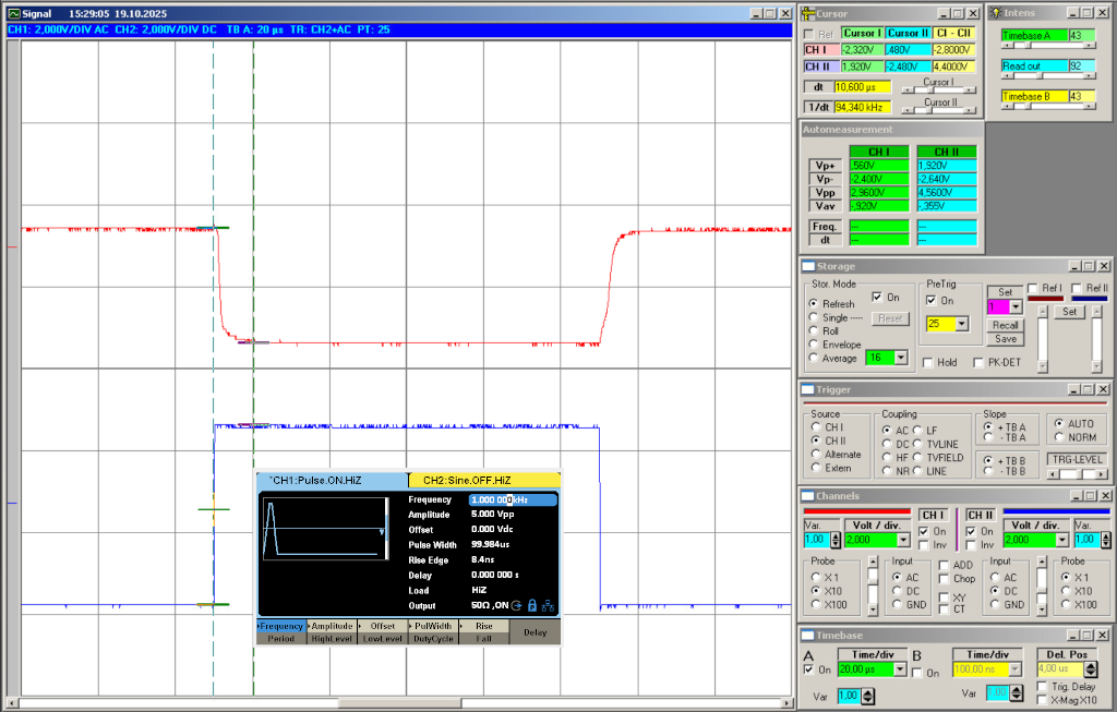
As working proof, some simple scope screenshots:
If you’re into optocouplers or small test circuits, feel free to build along or suggest tweaks.
Always happy to hear what others find useful in their own setups. 🙂
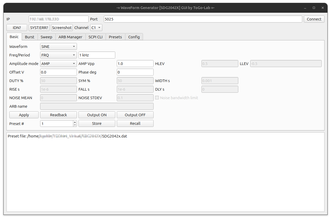
As part of rebuilding my electronics test bench for future projects at ToGo-Lab, I wanted a simple way to control my Siglent SDG2042X remotely from my Ubuntu box. So I wrote a small PyQt5 GUI script.
In its current state, the script lets you:
Select waveform, amplitude, frequency, and DC offset
Run sweeps, bursts, or arbitrary waveforms
Save and recall up to 10 presets (you can also recall directly from the generator)
Use the ARB Manager to download waveforms from the generator or upload new ones (not fully tested yet!) – it also shows the waveforms currently stored
Send direct SCPI commands through a built-in CLI
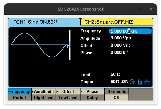
Grab screenshots from the generator display (saved in the same directory as the script)
Use it as-is or tweak it for your own setup. Programming in Python and PyQt5 isn’t my main profession -(I’m more of a hardware guy) so if you try it and find bugs (there will be some), I’d love to hear from you.
The program talks to the SDG2042X over a simple socket connection on port 5025 using SCPI commands.
You can call the script with the -ip parameter (try also --help). This is handy if you launch it via a .desktop file.
The functions are straightforward, so there’s no detailed documentation yet. I hope most of the features are self-explanatory. Each GUI tab covers one main function. See more details in the Gitea repo:
Basic: Waveform, frequency, amplitude, offset, phase, and output control
Burst: Configure burst mode, trigger source, cycles, and delay
Sweep: Set up linear or logarithmic sweeps, start/stop frequency
ARB Manager: List, upload, and download arbitrary waveforms (still experimental)
SCPI CLI: The command-line interface for direct SCPI communication
Presets: Store and recall up to 10 custom setups; presets are saved in a text-based .dat file. This tab is especially useful: You can adjust settings directly on the generator, then read them back and save them as presets. The file is easy to edit manually if needed.
You can take screenshots at any time. They’re stored as .bmp files in the working directory, with the date and time included in the filename.
Update 2025-10-25
My SDG2042X Python control GUI keeps moving forward. Today I spent a lot of time reviewing and rewriting parts of the code. My focus was on stability & usability, and making the tool to fit better into my idea of a remote controlled test bench setup.
Today’s update:
Context-aware Basic Tab
The parameter fields now change automatically depending on the selected waveform.
So if you choose SINE, SQUARE, RAMP, PULSE, NOISE, ARB, or DC, you’ll only see the options that actually matter, others are grayed out.
Improved SCPI Reliability
I added a new query_retry() function and a socket drain, which makes communication with the generator more reliable. This prevents annoying timeouts when running queries like OUTP? or BSWV?.
The default socket timeout has also been set now to 4 seconds to give things a bit more breathing room (especially the screenshots are very slow). This makes it a little bit laggy but with shorter time I get sometimes errors. Adjust with care if you want a shorter response time.
Config System
There’s now an SDG2042x.config file where you can define paths for presets and screenshots (simple text file).
The pathes for presets and schreenshot directory are accessable from the “Config” tab.
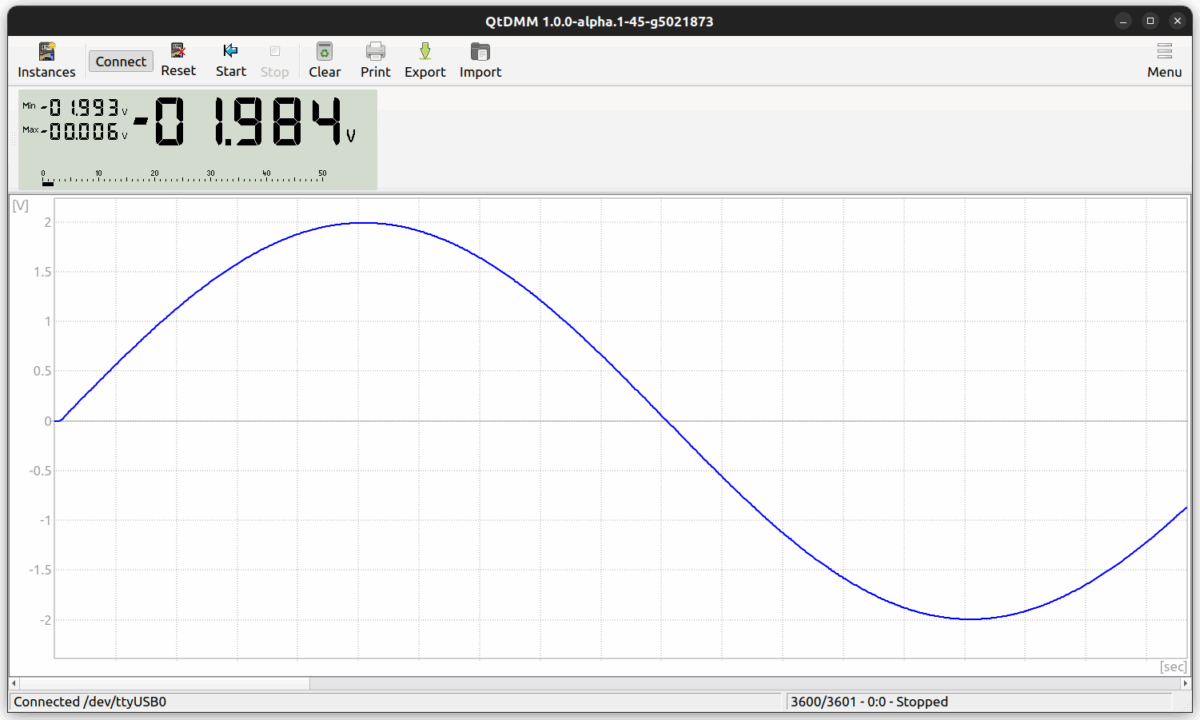
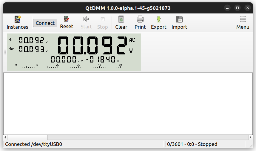
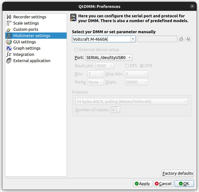
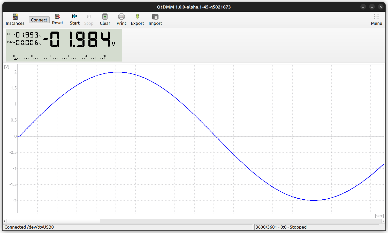
I pulled my veteran DMM, a Voltcraft MXD-4660A, from the drawer to set up my workbench (adding a serial-to-USB converter) and gave it a second tour of duty with QtDMM on Ubuntu. After a bit of searching online what to use under I found the QtDMM project at http://www.mtoussaint.de/qtdmm.htmlm , but appears abandoned. The active fork, I think, is at https://github.com/tuxmaster/QtDMM.
Here’s the final install and setup for my lab computer running Ubuntu 22.04 (Jammy):
# run from the same build dir used for the install
sudo xargs rm < build/install_manifest.txt
Troubleshooting:
If you hit errors, try a clean build reset instead of first searching forums.
I learned the hard way to make a clean install as a belt-and-suspenders reset, that deletes built objects but keeps the CMake cache.
“|| true” lets the sequence continue even if the clean step fails due to a broken config.
“rm -rf build CMakeCache.txt CMakeFiles” force-removes any stale out-of-source build dir and any accidental in-source CMake cache:
“Final ./compile.sh” does a fresh configure and build:
This is my first hardware project on the new ToGo-Lab.io server.
Some years ago, when I started with AVR/ATTiny programming, I built a tiny Morse “throwie”: one ATtiny, one LED, one resistor, and power-friendly firmware. The goal was to use as few parts as possible to keep it cheap, while still adding a couple of useful functions.
Two main functions: Detect daylight. If it’s bright, sleep; if it’s dark, send a Morse message. The LED doubles as a light sensor.
This is a good restart for my new project home, https://togo-lab.io/, the HW version of a “Hello World” program. So I don’t plan heavy hardware work here, though I may add a small solar cell to stretch battery life. This version adds a supercapacitor and small solar cells and uses the LED as a light detector, so it only blinks in the dark. It’s no longer a throwie, more of a pendant. Hang it where it gets daylight and stays dry. It charges by day and blinks by night.
Yes – I want also a PCB and maybe you will the final result as a little DIY Project on e.g. – Tindie.
But real goal is to define the specs and a simple, repeatable workflow from Idea to real DIY Kit especially for bigger future projects.
This post will evolve as the project advances. I’ll append notes, design decisions, and lessons learned rather than writing a single post-mortem at the end.
But don’t expect too much progress too quickly; this is a side hustle. Perhaps in a few years, after I retire, it will become one of my main activities.
What it is
DIY-Kit goal: beginner-friendly soldering kit with clear docs and hackable programm (using Arduino IDE).
MCU: ATtiny45/85, through-hole.
Power: 3–5 V, with solar + supercap option.
Behavior: Morse message presets, LED as light sensor for night-only blink.
Default license: CC-BY-NC-4.0 for docs and design files.
Roadmap
v0.1: Proto: breadboard + first PCB, single message, speed presets.
v1.0: Pilot: build guide, BOM with alternates, pilot of 10 units.
v1.1: docs polish, optional brightness setting, minor PCB tweaks.
v2.0: Zero Series
…
How this post will evolve
I’ll update this page with:
Schematics, Circuit description,
PCB Design, CAD. All you need to build one,
Build photos and assembly hints.,
BOM changes and sourcing notes,
Additional Blog post about the program itself and how to do with Arduino IDE.
Want to get involved?
Suggestions welcome. Open an issue on the repo or email tgohle@togo-lab.io.
If you build one, share photos and your timing results—those will feed back into the docs and the next revision.
I’m Thomas Gohle, and Tōgō Lab / 塔郷研究所 is my home base for future electronics projects.
About me: I studied RF communications in my youth, then spent the last few decades in semiconductor maintenance (details on LinkedIn).
I currently live in Dresden, Germany. With retirement on the horizon in some years, I’m rebooting my hobby. To my boss, if you’re reading this: it will take a while (you know how slow I can be). As you know I’m still working on current and upcoming equipment projects, and I still like to play with my wet-chemistry semicon beasts.
What can you expect? RF experiments, analog circuits, sensor builds and some digital electronics projects to some extend. I enjoy small AVR work, especially ATtiny. I document designs so they can be reproduced and improved by others. The midterm plan is to turn stable builds into small-batch kits and offer them to you. But making money is definitely not the goal of Tōgō Lab. The main goal is community, having fun, learning something new and doing things with my hands.
Collaboration lives on this server. Source code and issues are in Gitea at https://gitea.togo-lab.io. Shared docs and files that don’t fit into Gitea run through Nextcloud at https://nextcloud.togo-lab.io, which also supports basic project planning and control. This blog ties it together with build notes, measurements, and hard-won lessons. Some areas may be invite-only while the workspace settles.
Under the hood it’s a simple stack: Debian on a VPS and Apache with HTTPS via Let’s Encrypt, with a reverse proxy to services. I also keep a separate, older weblog you can find at my primary landing page https://tgonet.de. That older blog is shifting to private and travel notes (I like to travel, especially in the Far East), while Tōgō Lab here stays focused on electronics.
If RF, analog, and ATtiny projects are your thing, feel free to follow along, e.g., via my Mastodon account connected to Tōgō Lab. Ideas and pull requests welcome.